

The long weekend meant I didn’t have to stay up till some crazy hour of the morning to continue the build. The draw-back is I turned 40 and it was the first hot day of the summer (well Spring now but at 34c it may as well be summer).
Started early to try and finish the engine completely by 5pm – we didn’t get there.
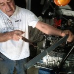
Fitted the inner 4 pistons into their cylinders easy enough using the special tool but 1 and 6 continued to be a problem. Hand fitted top and middle rings on piston 1 and 6 but the oil rings are both relatively brittle and very hard to compress (with their inner spring) so hand fitting them was not an option. We ended up using the humble stainless steel hose clamp which was narrow enough (but only just) to compress just the oil ring and allow the cylinder to come down over the piston and the oil ring and allow the removal of the clamp again. When I mean the clamp width just allowed the fitting of the final piston oil ring I mean just, if they were another millimeter wider there would not have been enough room to get piston into cylinder by dropping the cylinder block down on it. I’m sure you are asking yourself – why didn’t the fool just push the piston up into the cylinder by turning the crank? The problem is if you turn the crank to push the piston up into the cylinder pistons 3 and 4 will come back out of their cylinder resulting in a complete re-do of everything and a lot of swearing. After about 2 hours work the pistons and cylinder block were finally finished. If you are doing this job you need to keep in mind that the pistons will rock about a little in the cylinder while the pistons skirt isn’t available to keep it upright – this adds to the fun.
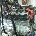
As we installed new cylinder O-rings (they fit over the base of the cylinders that poke into the crank case and seal the crank case to the cylinder block as well as a gasket) the cylinder block did not go all the way down but instead sat above the crank case by about 1 mm – this is due to the o-rings, its not till you torque the head will you compress the O-rings and allow a good fit.
On with the cylinder head, new head gasket and oil rings that continues the oil gallery running up to the head – there is no hollow dowel here continuing the oil gallery from the cylinder block to the head – just a bloody o-ring – why they didn’t fit a hollow dowel I can not understand. After torquing everything down with our old school torque wrench both the cylinder block and the head beaded down fine, however, the head gasket split right on the end of the head next to cylinder number 1 where the newly installed o-ring allows oil to continue up to the valves and cam. What I am thinking is that the oil ring expanded when the head was tightened and as it is contained within the head gasket its pulled it apart a bit. We pushed a bit of red goo into the section where the gap formed between head and cylinder block just in case. There is no knowing if the damage to the gasket is going to cause an oil leak or not till we start it up – i’m thinking we should be good but engines don’t think – they just do. I can’t see they split running all the way to the #1 piston and given each cylinder has a metal reinforced ring part to the gasket there shouldn’t be a problem with # 1 but again – engines will do what they do.
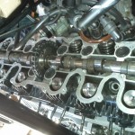
Next step was fitting the cam shaft and sprocket – this is a complete pain in the ass. The crank drives the cam chain which in turn drives the cam sprocket which is bolted to the cam makes it turn, however, the cam must be timed relative to the crankshaft so the valves open and close at the right time to let petrol and air in and let exhaust out, but, at just the right time to prevent valves being smashed by the pistons. Fitting of the cam shaft is from the right had side, first through the chain then through the cam drive sprocket. The cam sprocket has two cut outs which allows the sprocket to drop down just barely enough for you to wiggle the cam chain onto its teeth (and I mean just enough). The issue now is that the crank needs to be in a particular spot as does the cam shaft, however, the cam sprocket can not bolt straight onto the cam shaft in the position its was in when we were able to put the chain on – oh no, that would make life easy, its 20 degrees away from there. As there are only 3 holes in the cam sprocket available for you to bold it onto the cam, the cam sprocket must be fitted onto the chain in just such a way as to have one of the holes in it line up with the one bolt hole in the cam and have the crank in the correct position and have the cam shaft in the correct position. Its a nightmare to get this right and requires you to take the chain off the sprocket, rotate the crank back enough to get the cam sprocket to match the cut out to the top of the cam that allows you to drop the chain off the sprocket to then calculate where the sprocket should be when mounted on the cam to then be bolted onto the cam and have cam and crank at the correct position together. This bit must have taken us about an hour and a half of trial an error before we had the chain on the correct teeth of the sprocket.
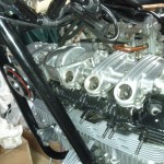
Now you can fit the cam box which has one huge O-ring as a gasket and around 30 hex-bolts to do up to complete it. The o-ring will fall out if you don’t use enough grease to stick it in. It was after this stage I found out we had set the crank in the wrong position relative to the cam by about 10 degree which translated to 20 degrees at the crankshaft as you turn it which resulted in the slow turn of the engine (after finally fitting the cam box) was meet with a sudden stop when valve contacted piston, however, it was a very gentle slow hand rotation for just such a reason. Off with the cam box, remove both cam sprocket retaining bolts, drop sprocket and re-time again to the correct spot again then put cam box back on etc etc. By now we had gotten a little quicker at this puzzle so it only took 40 mins. By 6pm we were done and the engine rotated freely. We tested the compression in each of the pistons using the starter motor 125 psi each which confirmed no damage done to the valves or issues (at this stage) with the split head gasket.
Now all there is to do is bolt on the engine breather (sits on to of the cam box), insert the exhausts, hook up fuel, re-fit coils and fire up!
what order to remove cam cover bolts also head bolts what torque settings for both 750sei cam spocket torque please
So sorry to take months to get back to yore comment. I would have removed cam cover from the the outside, working in, be buggered if I can recall torque settings for any of it. Perhaps just copy what Honda 400/4 setting are – I expect they are the same, if not very close.