
I seem to have gone down a rabbit hole that a few others I read about have travelled. It goes something like this. You have the remote need for some esoteric test equipment to work on radios and stuff and you are overcome by the shear beauty and horrifying complexity of HP’s equipment from the 70’s, 80’s and 90’s.
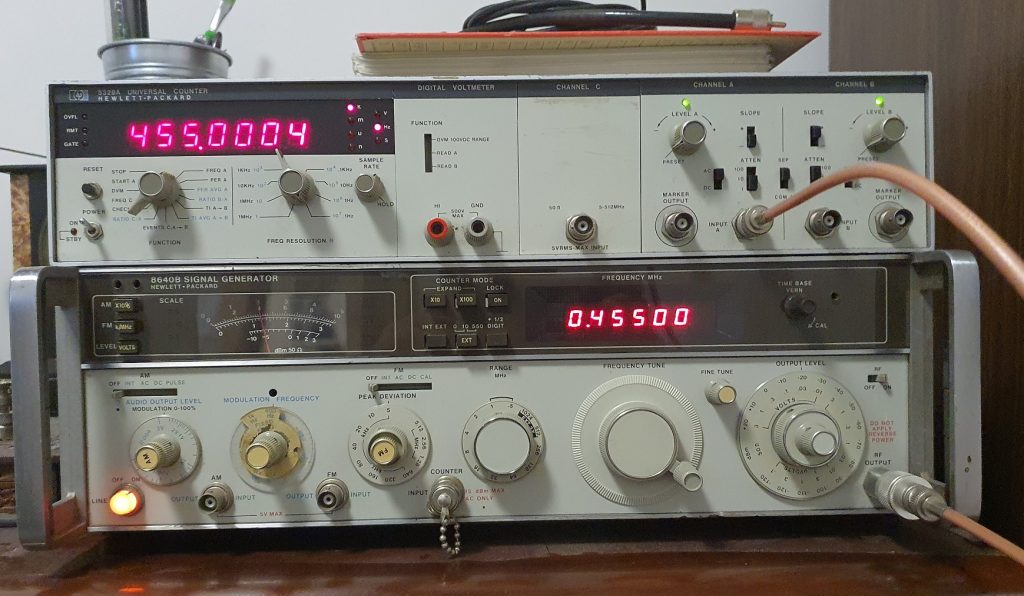
Truth be known, I had a frequency counter and a signal generator already but they were not what I wanted and so, during a car boot sale in August I purchased a HP 5328B for an amazingly reasonable amount given what they cost when new (this too seems to be a point many in my boat make). I couldn’t wait to get home and take a look inside. It has the crystal oscillator oven and seemed to me to be a lot larger and make a lot more noise than would be expected to perform this task but it is gorgeous inside with it’s 1970’s vintage gold trace PCB’s and red 7 segment display. This immediately led me to start searching for more HP equipment, the next being a signal generator.
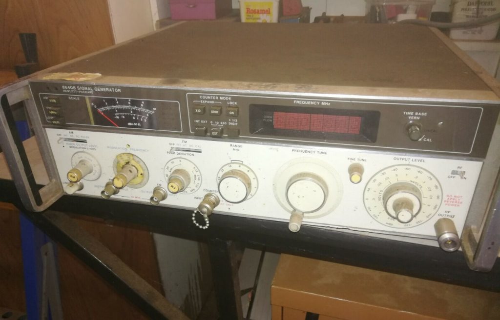
I was lucky to find one for sale on eBay, not working, from a chap here in Perth and so put and offer in for this HP 8640B and picked it up. Seem these units are used as a bit of a standard when it comes to quality of signals produced.
After getting it home and plugging it in, sure enough it did not work – the fan came on but there was nothing else working, no display, no needle movement – nothing.
POWER SUPPLY
First things first I ripped the top and bottom covers off and took a look at the power supply boards, all but 1 of the red LED’s were on, the one off was (from memory) the +5.2V rail. I noticed that the 0.022uF “Rifa” capacitor across the 240V in line had at some stage blown up and let out the magic smoke – this seems to be it’s normal mode of operation at this age and so I noted I should change that at some point but it isn’t going to stop the thing from running.
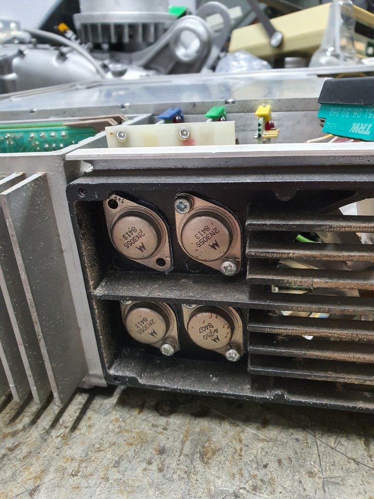
Pulling the A12 rectifier assembly I tested the multitude of diodes being used in the rectifiers. All diodes seemed to test fine so that wasn’t the problem. I removed the 3 voltage rail cards and re seated them, and I also removed the 4 power supply pass transistors and re seated those as well. Switching on after this finds all voltages are now present and the front numerical displays started working, however, despite my knob twiddling it only had a fixed range of frequencies, ie, changing the range selector had no effect, also, the FM modulation didn’t seem to work and the was no power output displaying on the needle.
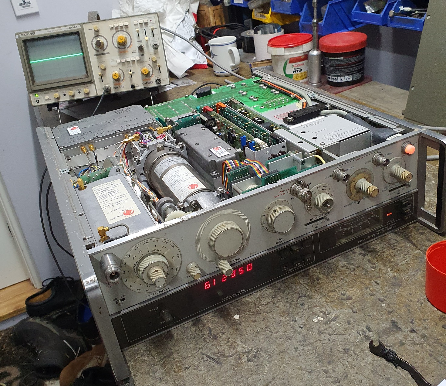
Later, a bit more fiddling with pass transistors finds one of the contacts on the power supply board that connects to one of the legs of a pass transistor had failed (broken) so I I’ll need to get a new connection for that at some stage as it is flaky.
ANALOGUE SWITCH LOGIC CONTACTS – RANGE & DEVIATION
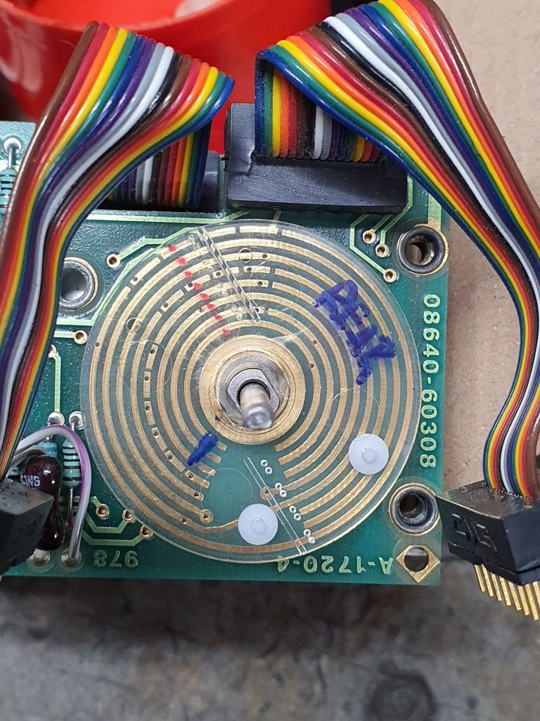
After a bit of reading I found that a common problem now days is the little contacts that rotate when you move the range switch, deviation and output level are getting to the age where the plastic welding holding them to the plastic switch disc is starting to fail. Sure enough, mine had the same problem and so it was time to pull these out and undertake a repair.
The first problem I encountered was the Allen key grub screws holding the knobs on these controls to the shafts on the switch mechanism. I loosened all but one of the grub screws (it’s always just one isn’t it) in the knobs, the last one ended up stripping internally so the Allen key just spun. A vain attempt to remedy the situation by gluing the Allen key in there with super glue and Devcon failed as expected. These grub screws are hardened of course so no normal drill can drill them out – I had to order a special 1.5mm solid carbide drill bit from RS Components to have any chance of drilling it out – this tiny bloody grub screw put a stop to the project for 2 weeks while I waited for the drill bit to arrive. After arrival of the drill bit I was able to drill out the grub screw – I’m sure this must happen all the time as the grub screws are very small – why they didn’t go larger I have no idea – seems plenty of room to go up a size or 2 on the range switch knob.
After finally getting the combined Range and Deviation switch mechanism out I found I was missing 5 of these little contact fingers across the 3 separate rotating plastic discs which had come loose and fallen off over the years into the bowels of the machine and despite my searching and shaking of the instrument, I could only find 2 rattling around in there so I had to make 3 new ones.
I ended up visiting my local electronics store and bought a range of components that I hoped could have internals that would work as replacement contacts, this range of components included an edge connector block which, after pulling apart had an almost endless supply of contacts if you undertook some modifications (see below). These replacements are made of a thicker gauge metal which may be a problem and one must remember to remove any sharp edges that may exist on the contact fingers (I used a very fine Arkansas sharpening stone) so as to not damage to PCB that it contacts with.
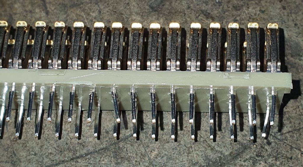
Edge connectors inside 
Modification of edge connectors
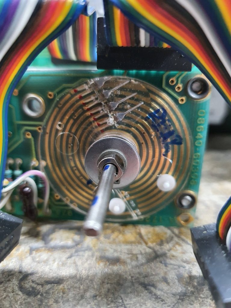
After using a 2 pack epoxy to glue the old fingers on again and also the 3 new made fingers I had the range function working again and the modulation selector seemed to work as well.
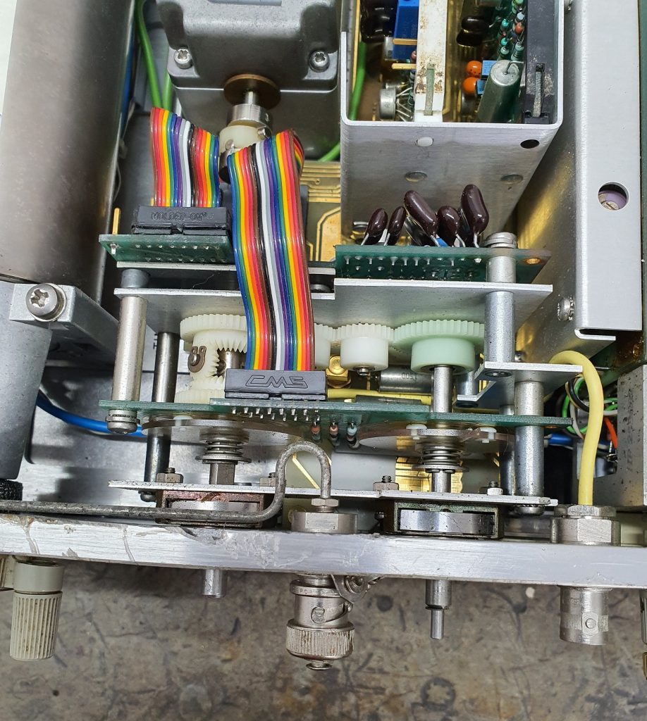
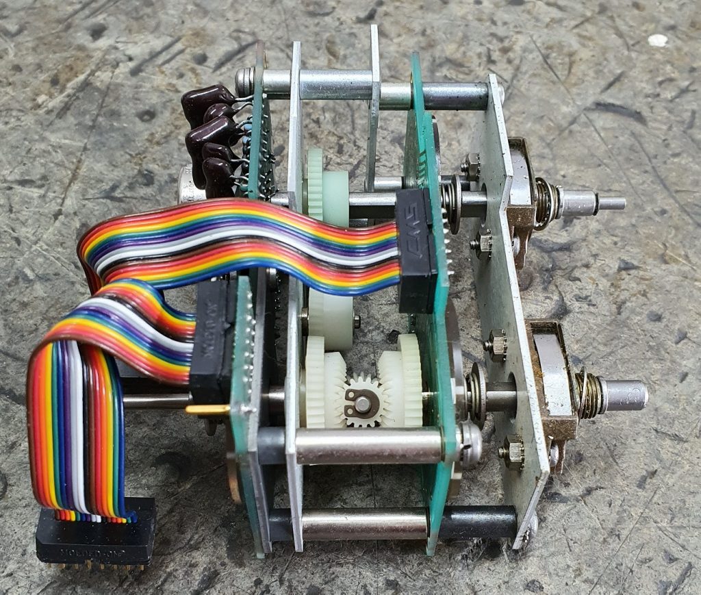
CRACKED RANGE GEARS
This too seems to be a common fault in these machines. Apparently the plastic used was called Delron and that has a tendency to shrink over the years causing stress cracks as the hub the gears are cast on is brass which will not shrink and so something has to give.
One of the bevel gears was badly cracked so I broke it completely and then glued it back again using epoxy. After drying one of the teeth just wasn’t quit lining up well enough to mesh properly and was jamming things up; a little bit of a file on the offending tooth to widen the gap was just enough to gain clearance needed and it all rotates as well as can be expected.
As a side note, remade solid brass gears are now available online which may be on the Christmas list this year.
OUTPUT POWER
Even after getting the range switch working the gauge showing output power was not registering anything (it worked when selecting AM or FM modulation % but not output level voltage). I tested the AGC board and its didn’t seem to be giving me the correct readings. A bit if hunting around and tracing resulted in me pulling out the output power selector/attenuator assembly which had another analogue switch rotor with the same little contact fingers on it. In place inspection the contacts looked to be there but on removal I see that 3 of them were broken and wouldn’t have been making good contact – if at all. Seems these contacts feedback into the AGC which in turn feeds to the power meter and so its an important part of the output circuit.
Gluing on these contacts and reassembly it all seems to work again, needle moves with changes in the output power vernier, annunciator lights work as expected. YOU RIPPER!!
CONCLUSION
This instrument is the first one I worked on and I learnt a lot. Just getting my head around the HP Service manual was a steep learning curve but I’m happy to have a fully functional signal generator. I have now sold my old signal generator and frequency counter and have these HP machines proudly in my office/lab. I plan to get a few more HP instruments, would be good to get a Spectrum Analyser so am on the look out for a broken one to try my luck again.
Hi Martin
After reading your blog, I am so impressed with your perserverence and tenacity to restore the sig gen.
Many years ago I was also similar to you and loved making broken equipment work again but of late that drive had disappeared. I can now get my buzz by seeing that there still a few people in the next generation that appreciate quality equipment and have the get up and go to restore it rather than just throw it away and buy a new piece of Chinese junk that is designed and built to only have a very short lifespan
Thank you Keith for the kind words.